
Image Library
2004 March - Goddard - Instrument Awating Testing
The WFC3 instrument integration at the Goddard Space Flight Center is nearly complete. Both flight detectors have been integrated. The instrument is undergoing final check-out and close-out activities prior to commencing the ambient calibration and thermal vacuum testing.
 |
 |
 |
2003 May - Goddard - Refurbished Radiator
The radiator is the only portion of the instrument that is exposed to space as it curves along Hubble's outside shell. The radiator of WFPC1 is refurbished for WFC3. Not only is it repaired, resurfaced, and repainted, but physical and electrical reconfigurations are made to accommodate the mechanisms of WFC3.
 |
 |
 |
2003 May - Goddard - Optical Bench into Enclosure
Having been worked on separately for over a year, the main enclosure and the optical bench come together as the latter is carefully inserted into the former.
The flat metal plate shown in the top center image is WFC3's cold plate. It goes beneath the optical bench on the floor of the main enclosure.
 |
 |
 |
 |
 |
 |
2002 Jul - Goddard - Main Enclosure Tests
 |
 |
 |
 |
 |
 |
2002 Jul - Swales Aerospace - Optical Components
All incoming light goes through these components before it hits the light detectors of one of the two channels (UVis & IR). Click here to see part descriptions.
 IR Filter Wheel |
 UVis Filter Assembly (SOFA) |
 UVis Shutter Device |
 IR Cold Enclosure |
 Tip/Tilt Corrector |
 Channel Select Mechanism |
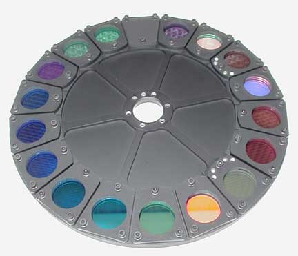
2002 Nov - Swales Aerospace - Filters
Filters deterimine which wavelengths of light reach the light detectors. Top row: UVis Filters and wheels. Bottom row: IR filters and wheels. Click here for more info on WFC3's filters.
 |
 |
 |
 |
 |
 |
2001 Aug - Swales Aerospace - A New Optical Bench
The WFC3 optical bench panels have been fabricated and cleaned. They are presently being assembled at Swales Aerospace. The panels are constructed of graphite composite face sheets and aluminum honeycomb core.
 |
 |
 |
 |
 |
 |
2001 Sep - Johnson Space Center - Zero-G Simulation
In the Neutral Buoyancy Lab (NBL) at Johnson, astronauts train underwater to simulate zero-gravity conditions. Here they release a WFC3 mockup from a carrier and angle it over to a Hubble simulator for insertion.
 |
 |
 |
 |
 |
 |
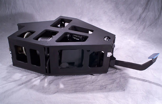
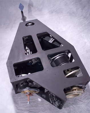
2000 - 3D Models of WFC3's Outside
The pick-mirror is at the "tip" of WFC3. It directs incoming light into the instrument. The rounded structure at the "back" of WFC3 is the radiator which will become part of the outer shell of Hubble to expel heat into space.
 |
 |
 |
 |
 |
2000 - 3D Models of WFC3's Inside
The first row shows WFC3 with its top off. The optical bench can be seen (dark blue structure) as well as the electronic boxes. The bottom row shows the optics of WFC3 through a transparent optical bench.
 |
 |
 |
 |
 |
 |
1999 Apr - Goddard Systems Lab - WFPC1 Deintegration
WFPC1 is carefully positioned for deintegration (disassembled). In the bottom row of pictures, you can see that the optical bench has been removed from the main enclosure.
A new optical bench will be fashioned for WFC3; however, some of the optical components inside the bench will be taken out and reused for WFC3. The main enclosure and radiator will also be reused for the new instrument.
 |
 |
 |
 |
 |
 |
1999 Feb - Goddard Systems Lab - WFPC1 Different Views
WFPC1 in the Systems Lab for Alignment and Calibration (SLAC). From the different picture angles, you can easily see the radiator (white curved structure), the main enclosure (tan-trimmed framework), and the optical bench (black holed object inside).
 |
 |
 |
 |
1998 Aug - Goddard Cleanroom - WFPC1 Prep
Many of Hubble's parts and instruments are built and tested in Goddard's cleanroom. WFPC1 is prepared for its deintegration so that its parts can be used for WFC3. The captions below refer to the left wide-angle image.
 |
 |
Center - The pie-shaped structure is WFPC1.
Far Wall (grid) - WFPC1 points at the the Hubble mockup (High fidelity Mechanical Simulator or HFMS).
Top Right Corner - The tan round structure is the electrical simulator for the Hubble Space Telescope.
Right Wall - Along the right wall is one of the carriers used to carry scientific instruments into orbit aboard the shuttle.
Left Wall - Along the left wall is the Flight Support System (FSS). During servicing missions in space, it attaches Hubble to the Space Shuttle.

A close-up of WFPC1 and the Hubble mockup (HFMS) is shown in the left and middle images. The top rectangular hole on the mockup is where WFPC1 was taken from on the real Hubble. |

A close-up of WFPC1 and the Hubble mockup (HFMS) is shown in the left and middle images. The top rectangular hole on the mockup is where WFPC1 was taken from on the real Hubble. |

The WFPC1 is being moved by a counterbalance fixture. This fixture also serves to approximate a 0-g environment for astronaut training. |

The external radiator of the WFPC1. The radiator was exposed to space as part of the outer-shell of Hubble. The panel in the center provides access to the power supplies in the instrument. |

Side view of the WFPC1. The inner black box with rivets is the main enclosure of WFPC1. The aluminum structure framing the WFPC1 is a transport fixture that secures the location of the latches on the instrument. |

This is the view of the instrument from the end that is inserted into Hubble. The Pick-off Mirror is obscured by the aluminum fixture. |

- Curator: J.D. Myers
- NASA Official: Phil Newman
- Science Official: Kenneth Carpenter
- › Privacy Policy and Important Notices
- › Contact NASA
- › Fermi FAQ, Comments, Feedback
- › Page Last Updated: Wed, Mar 14, 2012