This webpage is kept for archival purposes only and is no longer updated or maintained.
Components & Parts
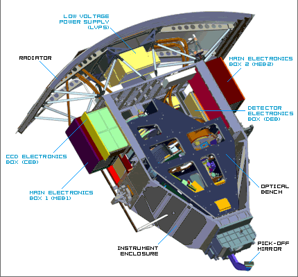
A schematic of WFC3 is shown below. Point the mouse on the different buttons to view WFC3's two optical channels. The dual channels give WFC3 a wide range of vision across the Spectrum from near-UV to visible to near-IR.Main Components

Structure and Framework
- Pick-Off Mirror - Mirror that directs light from Hubble's focal plane into WFC3's optics.
- Instrument Enclosure - WFC3's primary casing and framework for its mechanical and electronic parts. It is made mostly of aluminum 6061.
- Optical Bench - Structure that contains WFC3's optics. The bench is made of a Graphite CySi/Aluminum alloy.
- Radiator - The "outside" of WFC3 that is exposed to space. It expels heat out of Hubble and into space through black body radiation.
Electronics
- Main Electronics Boxes (MEBs) - Contains electronics that support WFC3 primary systems for operation.
- Low Voltage Power Supply (LVSP) - All of Hubble's power is supplied by its solar panels and stored in batteries. The LVSP routes Hubble's power into WFC3.
- CCD Electronics Box (CEB) - Contains the electronics for the UVis channel's Charged Couple Device (CCD).
- Detector Electronics Box (DEB) - Contains the electronics for the IR channel's detector (located beneath MEB2).
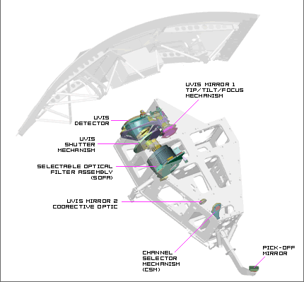
UVIS Channel Components

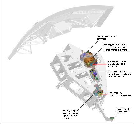
IR Channel Components

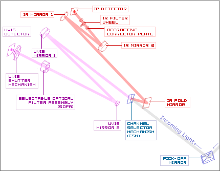
UVIS & IR Channel Components - Optical Configuration

- Pick-Off Mirror - Mirror located outside of WFC3's main enclosure, which "picks-off" light from Hubble's focal plane and directs it into WFC3.
- Channel Selector Mechanism - In its "on" position, this mirror reflects incoming light into the IR channel. In its "off" position it moves out of the way to allow incoming light straight into the UVIS channel.
- UVIS Mirror 1 - The first mirror of the UVIS channel. This hyperbolic mirror is attached to a tip/tilt & focus mechanism.
- UVIS Mirror 2 - The second mirror of the UVIS channel. This mirror contains corrective optics (anamorphic asphere) to compensate for Hubble's sperical aberration in its primary mirror.
- Selectable Filter Assembly (SOFA) - This mechanism switches out the optical filters that will determine what wavelengths of light will reach the UVIS detector.
- UVIS Shutter Mechanism - This device determines when to let light hit the photo-sensitive detector. Unlike most cameras, the UVIS shutter can allow day-long exposures rather than ones that last for just fractions of a second.
- UVIS Detector - The UVIS channel utilizes Charge-Coupled Device (CCD) detector technology like most digital cameras. Its photosensitive material converts light into electrical charges that can be recorded as data.
- IR Optic Fold Mirror - Flat mirror of the IR channel, which redirects light to the rest of the IR channel from the Channel Selector Mechanism.
- IR Mirror 1 - This hyperbolic mirror of the IR channel focuses the incoming light into a tighter beam.
- IR Mirror 2 - Elliptical mirror of the IR channel that is attached to a tip/tilt & focus mechanism. It directs light to the IR detector.
- Refractive Corrective Plate - This translucent plate contains corrective optics to account for Hubble's spherical aberration in its primary mirror.
- IR Filter Wheel - This mechanism switches out the optical filters that will determine what wavelengths of light will reach the IR detector.
- IR Detector - The IR channel utilizes a Mercury Cadmium Telluride detector. Different detector types are used in the two separate channels because they are more sensitive to their respective wavelength ranges.


