|
Different tests are done on the finished
CCD packages depending on what the CCD was made for. Scientific
instruments will need different tests performed than a
final product meant for a dental application. These are
all determined by the clients needs.
Slow Scan Cameras
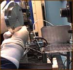
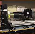
The Slowscan 3 camera allows us to grab individual full-frame
images from the CCD under test, under various illumination
and driving conditions. The image data is then placed
in a Framestore, and analyzed using a number of specially
written software routines in order to characterize the
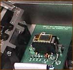
performance of the CCD. The CCD is held in a purpose-built
jig within the camera head, and cooled to -83degC using
liquid nitrogen. The camera head and CCD chamber are pumped
down and held in a vacuum, to prevent icing-up of the
device, which would occur if it were cooled at atmospheric
pressure. A checkerboard-patterned test chart is used
to obtain an image for checking basic functional test.
The device can be driven in different modes for different
tests using a collection of Timer Files. These are written
and stored on the PC, and called up in turn to generate
a variety of particular clocking sequences. The Electronics
rack contains the clock buffering for driving the CCD pulses,
and the 16-bit digitizer, which converts the CCD analogue
output waveform to digital data for storage and analysis
on the PC. The computer-controlled CCD bias voltages are
generated within the rack electronics, which also houses
the temperature controller for the CCD.
| Testing Demonstration |
Laser Testing |
Slow Scan Camera 3 |

|
 |
 |
Previous Step :: assembly
|


